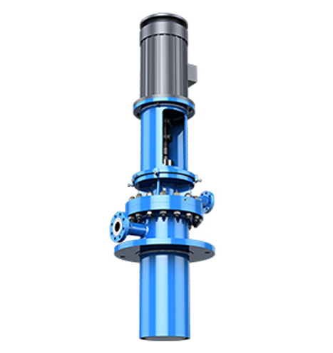
LC vertical long axis turbine pumps Assembly
1. Preparations for LC vertical long axis turbine pumps before Assembly
(1) vertical long axis turbine pumps can be assembled only after inspecting whether the parts have defects that affect the assembly and scrubbing them clean before assembling.
(2) Check the coordination of all parts: check the coordination of keys and shafts, keys and impellers; check the coordination of flat keys, clasps and sleeve couplings and shafts; check the coordination of impellers, sleeves, sleeve couplings and shafts, and keep the radial clearance between sleeves and guide bearings between 0.15 and 0.25 mm, etc.
2. LC vertical long axis turbine pumps Component Assembly
(1) The sealing rings are respectively mounted on the bell mouth and the guide vane body, and are equipped with seam bolts.
(2) The guide bearing is respectively loaded into the guide bearing bracket and the guide vane body. Packing bushing is packed into packing box, pay attention to the key and hole retaining ring.
(3) Small assemblies of thrust bearing components: the oil-proof bucket is fixed on the bearing body, the outer ring of thrust bearing is loaded into the bearing body, the inner ring is loaded into the transmission sleeve, the transmission sleeve is loaded into the bearing body, and the bearing cover is fixed on the bearing body.
(4) Small fitting of intermediate axle: Insert sleeve on intermediate axle, install shaft with retaining ring, and fix with screw.
(5) Small mounting of transmission shaft: Insert O-ring on transmission shaft, then install packing sleeve and shaft retaining ring, and fix with screw.
3. LC Type vertical long axis turbine pumps Assembly
vertical long axis turbine pump assembly adopts vertical or horizontal.
(1) Install the impeller shaft on the sleeve, key and last stage impeller, and then guide it into the last stage guide vane body.
(2) Shielding, next stage bushing, guide vane body, key and impeller (two or more pumps). Repeat the process until all the secondary impellers are installed.
(3) Install shield, sleeve, primary guide vane body, primary key, impeller, stop washer, lock impeller nut, install bell mouth and filter.
(4) The key and sleeve coupling are arranged on the middle axle in turn, and the impeller shaft and the middle axle are connected by a half-clasp and sleeve coupling, and the shaft is loaded into the slot with a retaining ring. The O-ring is installed on the last guide vane, and is introduced into the guard pipe and the riser pipe. The guide bearing bracket (O-ring is installed on the bracket) is pressed with bolts. When erecting, the pump is transferred into the pit and supported by channel steel on the footboard of the riser. In this order, the intermediate shafts, protective pipes, water pipes and guide bearing brackets at all levels should be installed until the transmission shafts, protective pipes and water pipes are adjusted.
(5) Connect the inflow and outflow elbow with the adjusting riser; install the O-ring at the filler box, align the adjusting guard tube, install the filler box on the outlet elbow, and install the packing cap.
(6) Install the key on the transmission shaft, install the thrust bearing components on the outlet elbow, and rotate into the round nut.
(7) Key and pump coupling at pump coupling.
(8) Fix the motor base on the outlet elbow.
(9) Adjusting the two round nuts on the thrust bearing to lift the rotor, the lifting amount of the rotor is 1/2 of the total channeling of the rotor. The turning is flexible without stuck and sluggish phenomenon.
(10) Oil loading standard (carving oil level line on oil mark), filler leakage pipe, external bearing cooling water, guide bearing lubrication pipe and other accessories.
If the thrust of the vertical long axis turbine pum is borne by the motor, there is no thrust bearing component in 3.6. The rotor is lifted by adjusting disc of the pump coupling, and the lifting amount of the rotor is 1/2 of the total channeling amount of the rotor.

Be careful:
1. In the above-mentioned assembly process, some small pieces, such as flat keys, water retaining rings, O-ring in the bush, are easy to be omitted or misplaced, so special attention should be paid.
2. Transport clear water, guide bearings if not prepared to pass cooling and lubricating water, can not install protective pipes.
3. In the case of insufficient lifting height, the installed part should be suspended and installed in the pump pit, and the filter screen should be installed before the pump pit is lifted, and the guide bearing lubricated water pipeline should be assembled synchronously.


